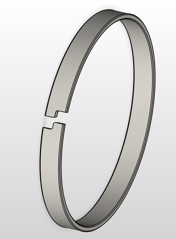
Version 5.4.4.9 (10 May 2024) introduces the radial z cut.
This live tooling operation available on profiles that have the option to be set as solid or split (for example GR01) automatically calculates the needed diameter to machine the tube so that the final dimension of the resulting part – after joined – equals the nominals selected.
What is needed?
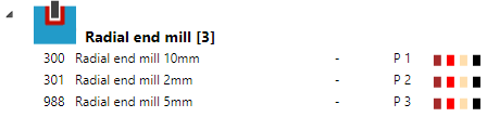
A machine able to use live tooling, the live tooling code set up and a radial end mill (recommended 2mm or less)
Example of set up Siemens 828D
1) Tooling
2) Live tooling code set up
On the machine settings the live tooling code must be set that matches your machine. In this example a Siemens 828D control is used, without the use of Delta2 variable. It can be modified to suit your machine.
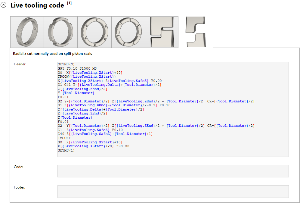
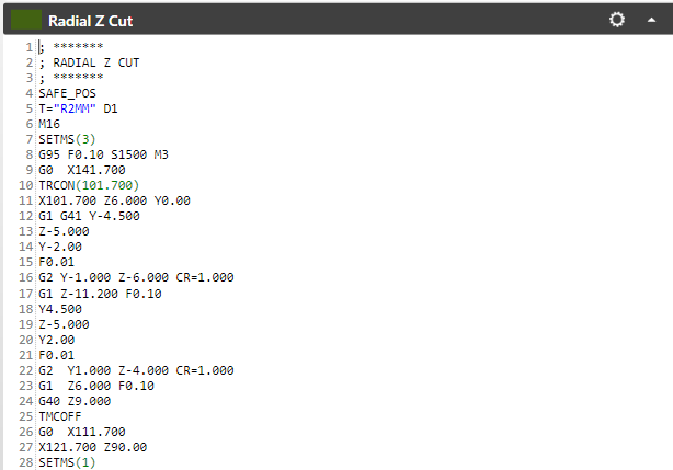
The content of the code is (can be used for copy paste):
Example for a Siemens 828D, without the use of Delta2 – others controls should use different codes/syntax
SETMS(3)
G95 F0.10 S1500 M3
G0  X[{LiveTooling.XStart}+40]
TRCON({LiveTooling.XStart})
X{LiveTooling.XStart} Z{LiveTooling.SafeZ} Y0.00
G1 G41 Y-[{LiveTooling.Delta}+{Tool.Diameter}/2]
Z[{LiveTooling.ZEnd}/2]
Y-{Tool.Diameter}
F0.01
G2 Y-[{Tool.Diameter}/2] Z[{LiveTooling.ZEnd}/2 - {Tool.Diameter}/2] CR=[{Tool.Diameter}/2]
G1 Z[{LiveTooling.ZEnd}-{Tool.Diameter}/2-0.2] F0.10
Y[{LiveTooling.Delta}+{Tool.Diameter}/2]
Z[{LiveTooling.ZEnd}/2]
Y{Tool.Diameter}
F0.01
G2  Y[{Tool.Diameter}/2] Z[{LiveTooling.ZEnd}/2 + {Tool.Diameter}/2] CR=[{Tool.Diameter}/2]
G1  Z{LiveTooling.SafeZ} F0.10
G40 Z[{LiveTooling.SafeZ}+{Tool.Diameter}+1]
TMCOFF
G0  X[{LiveTooling.XStart}+10]
X[{LiveTooling.XStart}+20] Z90.00
SETMS(1)
That is all that is needed. In this example polar coordinates are used. Let’s see how this works out.
Example of machining
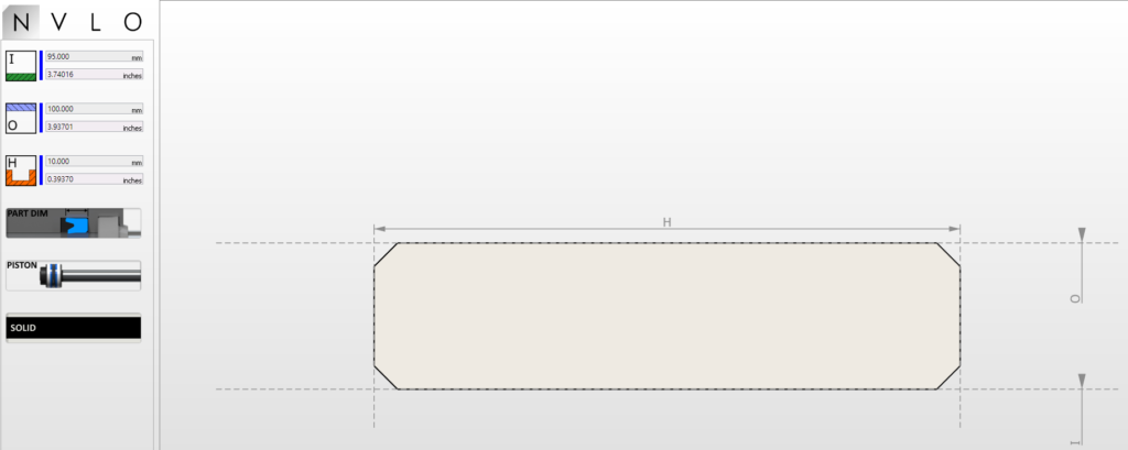
In this case we will machine a GR01 95x100x100:
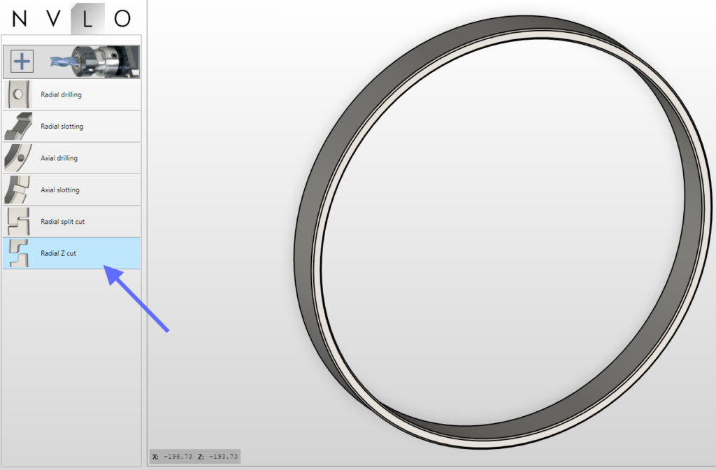
on the live tooling menu, choose the radial z cut:
This will open the operation menu. Here the smaller tool from the available list of tools will be selected. Automatic settings will apply that the user can change:
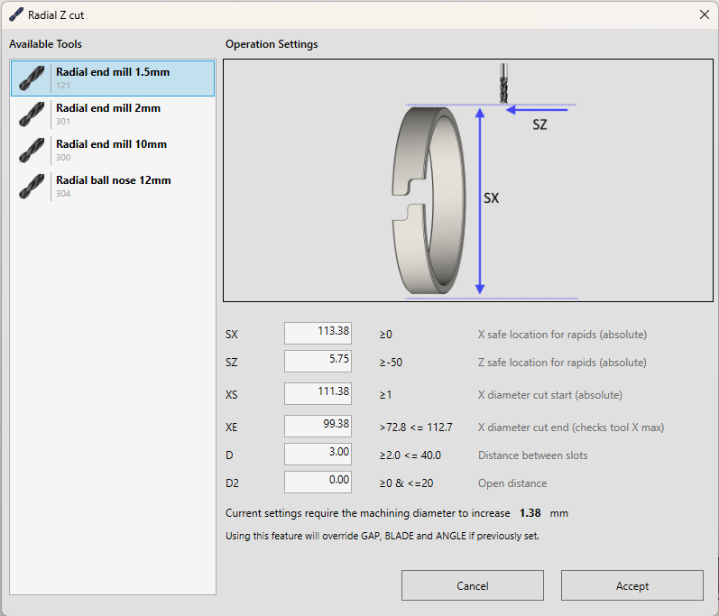
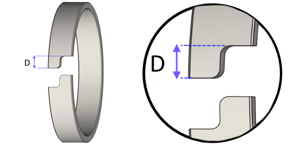
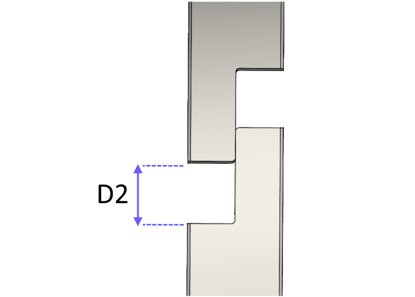
As can be observed, a indication of the amount in diameter that is needed to be increased on the machining part is calculated automatically. If the operation is accepted, those changes will be applied and the part will be machined with new diameters. This is performed internally changing the ANGLE, GAP and BLADE variables, therefor those should not be changed by the user. The parameters D and D2 refer to:
Also a preview is shown:
All those settings will result on the following code (example with D2 set to zero):
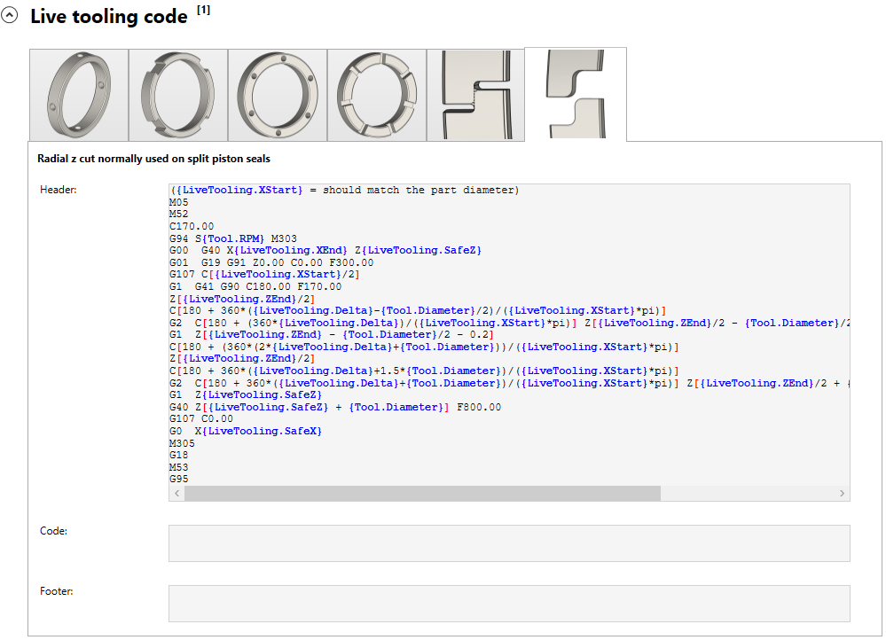
Example of set up Fanuc 0i-TD
({LiveTooling.XStart} = should match the part diameter)
M05
M52
C170.00
G94 S{Tool.RPM} M303
G00  G40 X{LiveTooling.XEnd} Z{LiveTooling.SafeZ}
G01  G19 G91 Z0.00 C0.00 F300.00
G107 C[{LiveTooling.XStart}/2]
G1  G41 G90 C180.00 F170.00
Z[{LiveTooling.ZEnd}/2]
C[180 + 360*({LiveTooling.Delta}-{Tool.Diameter}/2)/({LiveTooling.XStart}*pi)]
G2  C[180 + (360*{LiveTooling.Delta})/({LiveTooling.XStart}*pi)] Z[{LiveTooling.ZEnd}/2 - {Tool.Diameter}/2] R[{Tool.Diameter}/2]
G1  Z[{LiveTooling.ZEnd} - {Tool.Diameter}/2 - 0.2]
C[180 + (360*(2*{LiveTooling.Delta}+{Tool.Diameter}))/({LiveTooling.XStart}*pi)]
Z[{LiveTooling.ZEnd}/2]
C[180 + 360*({LiveTooling.Delta}+1.5*{Tool.Diameter})/({LiveTooling.XStart}*pi)]
G2  C[180 + 360*({LiveTooling.Delta}+{Tool.Diameter})/({LiveTooling.XStart}*pi)] Z[{LiveTooling.ZEnd}/2 + {Tool.Diameter}/2] R[{Tool.Diameter}/2]
G1  Z{LiveTooling.SafeZ}
G40 Z[{LiveTooling.SafeZ} + {Tool.Diameter}] F800.00
G107 C0.00
G0  X{LiveTooling.SafeX}
M305
G18
M53
G95
That corresponds to the setting (just copy and paste):