Feature availability: version >= 5.4.0.0
Status: Under testing
This post is a resume from start to finish on how to import a DXF file.
Step 0 – What is needed:
- A DXF with a correct drawing – see notes on correct DXF file
- A user with access level equal or higher than 1
Step 1 – Browse to ‘DXF Imported’ folder and select ‘New Profile’

Note: Inside the DXF Imported, folders can also be created.

Step 2 – Browse to ‘DXF Imported’ folder and select ‘New Profile’
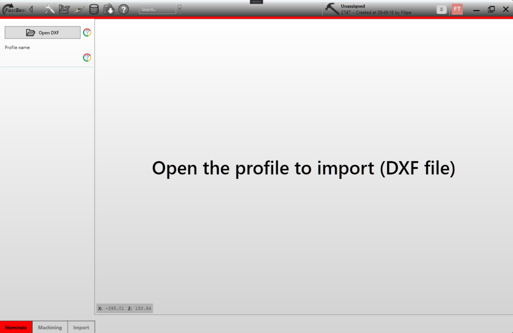
The following screen appears where the user is asked to open the source DXF file.

after selecting the file, a similar screen like the following is presented:

Four important groups of information are shown:
- The profile preview – that should correspond to the source DXF
- The nominals – nominals are automatically detected based on the top most point, bottom most point and height of the profile
- Material selection – User can define in what material this profile is mostly made off
- The DXF load results information – on this window some important information is presented so that problems with the source of the DXF can be tracked. Most common errors are the presence of elements that are not possible to import. To know more about the DXF please check Open DXF post.
2.1 – Detailed information about the DXF load results
The DXF load results window can help diagnose possible errors of the DXF file being loaded. Taking the example above the contents are:
- File path: Corresponds to the path of the origin file
- File size: File size on disk. Unusual files are discarded and cannot be loaded. Having a large file normally indicates that the file is not suitable to be imported.
- DXF version used. Versions up to 2015 should be loaded without issues.
- Number of layers present on the file. 1 is the expected number of layers.
- Number of blocks. Does not interfere with the output, but as a general rule, the file should not have many blocks.
- Lines: Number of lines present on the file that makes part of the profile geometry.
- Arcs: Number of arcs present on the file that makes part of the profile geometry.
- Other entities: if other entities (different from arcs or lines) are present, its numbers are listed here.
- Error list/resume window: A resume is present to the user with the most common causes listed. In the example, no issues were found.
Step 3 – Machining options
After loading the file and selecting the raw material, the machining tab can be selected.
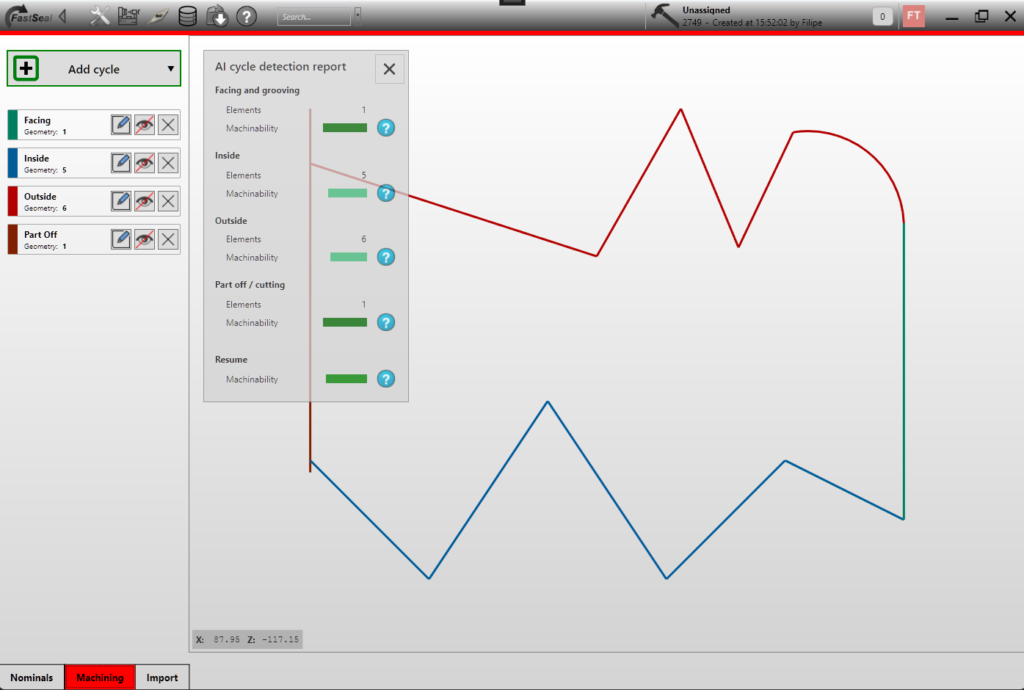
When entering the machining tab, the facing, inside, outside and cutting cycles with start to be automatically detected and again a pop up window will appear with the detection results.
Cycles can also be added with the button Add cycle, but currently the support for this functionality is limited and not recommended to be used.

On the main window, the colours represent the cycle to witch each geometry was assigned to. The pop up also provides information about the “machinability” rating, where shapes that are easily machined are provided a high rating. More information can be found leaving the mouse over the (?) marks on each machinability information.
For each cycle, the user can edit, hide or remove using the corresponding controls:

Hide/show cycle: Will highlight or remove the highlight of the elements that belong to the cycle. This function is usefull to check if there are other cycles also with the elements.
Cycle Removal: Removing the cycle will prevent that code is generated and will also “free” the elements associated with the cycle itself.
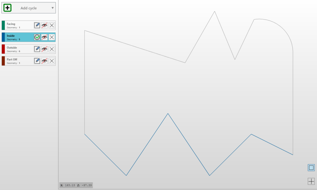
Cycle edit: Provides to the possibility to override the automatic selection of elements, adding or removing. When this option is selected only the selected cycle is presented and 2 selection modes are shown on the bottom right corner. Below example for inside machining edit mode:

The selection modes are “single mode” that is represented by a square and “area” mode that is represented by a cross.
- Single mode, the user can select and un un/select elements clicking on them:

- Area mode, more than one element can be un/selected as the user will be able to create a rectangle:

To stop editing the profile, simply select again the edit button on the cycle list.
Step 4 – Import
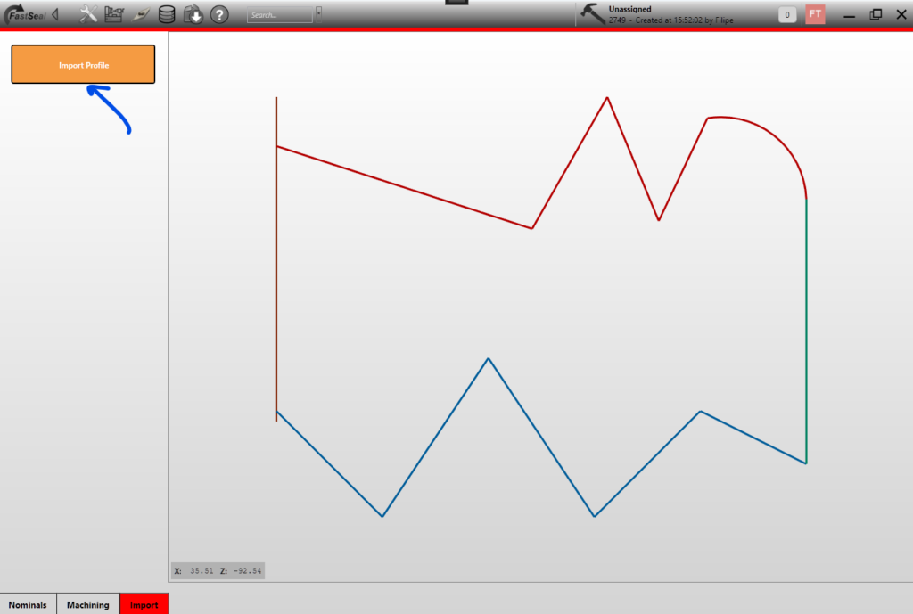
Finally the import tab provides the user with the ability to effectively import the profile.
More options will be added here during the software development and after feedback is received from customers.

After it is imported, it will be present on the imported profiles folder and can be machined.
