Each cutting tip can have different settings that defines how the tool is used by the software.
The user can add, edit, clone and delete tools to suit their exact tool system.

Basic settings
The basic settings of each tool are defined as follows:
Description
A small text to help to identify the tool. It have no internal function.
Number/offset
A unique number that defines the tool. It can range from 1 to 999. When the user needs to use a already in use offset, the current one needs to be deleted as offsets are unique (cannot be repeated).
Slot
A number that indicates where the tool is positioned on the turret. It can be left empty for machines that do not use a fixed turret location. This value is frequently used on the machine setting “tool change template” to define the tool call.
Alternative slot
A number that indicates where the tool is positioned on the turret when the primary number is already used by another tool.
Available
If a tool is not available, simply unselect the check box, that the g code generator will not attempt to use the current tool.
Radius
The tool radius tip is defined here. This value is important as most of the tool path generator makes calculations based on this value. It should match the tool in use.
Group
Select the correct group from the combo box selection. The tool will then taken in consideration when a determined group is needed.
Tip direction
Select the tool tip direction based on the image below:

More information here: https://www.fastseal.eu/blog/tool-tip-direction/
Tool geometry
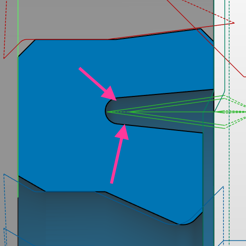
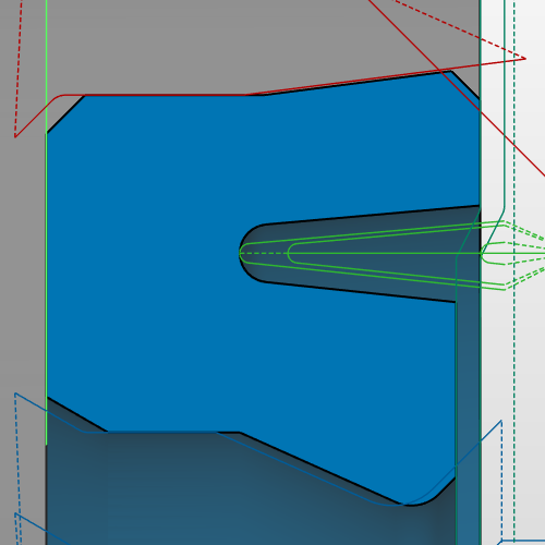
Select from the combo box the correct shape of the tool. The content of the combo box depends on the tool group currently selected. This tool geometry affects how the tool path is calculated so that there is no “over machining” of the final part. Below an example on how this can influence a groove tool path. The same applies for others tools and tools groups.


Spindle direction
Select the direction of the spindle for the current tool (clock wise or counter clock wise).
Advanced settings
The advanced settings of each tool are defined as follows:

Extra info
The extra info, is a completely free user string that will be attached to the tool and can be later be used as a reserved word. The most common use is on a tool change although it can be used on other settings. As a example if the user inputs on this dialog “T0101_T0113” D2, and on the tool change template (machine settings) the tool change is defined as:

The tool change will then be “T0101_T0113” D2 when this tool is going to be used. On Sinumerik machines this setting is often used.
This setting can be left empty if there is no need to use it.
Holder angle
Most of the tool holders have a built in angle. This angle is needed to be set up, so that the g code generator takes in account the geometry that can be machining with the current tool. The following complements this information:


This setting is shown/available depending on the tool group.
Priority
The g code generator will search for the most suitable tool for a determined task. When a suitable tool is found, it will be used to generate the code and the remain tools are discarded, even if suitable to produce the code. During the search for the suitable tool, a list of tools is created and sorted based on the priority value. The tools with priority “1” are placed on the start of the list while highest values of priority means that they have a lower priority. This means that tools with priority 1 are verified for compatibility with the current code, then priority 2 and so on.
If two tools have the same priority, the offset number will be used to sort the list.
Simultaneous offset on holder
Tools that share the same holder must have the information set. This will inform the g code generator that more than one offset is available while just one slot is in use. The syntax is offset-offset.
As an example, tool 1(outside elastomers) is on the same offset as tool 13 (inside elastomers), so on both tool 1 and on tool 13, this setting should contain the text 1-13 as shown on the example.
Restrictions
There are several restrictions built in the software based on the tool group. The restrictions are used to exclude the tool based on some conditions.
The current implemented restrictions are:
- Angle – Used on outside angle groove, this angle reflects the tool angle. If the geometry have a different angle, the tool is discarded as the final shape will not match the tool shape.
- Maximum outside diameter – On some machines, there is a maximum diameter value to use a tool. After that value another tool or set up is needed. To define (if existing) such limit to reject a tool, it should be inserted here. More information about this setting here: RestrictionsMaxOutsideDimension
- Maximum inside diameter – For drills, this option is available. The user can set the maximum diameter of the inside material on witch the tool can be used. If set as zero, only on solid materials the drill can be used.
- Maximum and minimum pitch, thread angle – All related with threads, it will restrict the use of the tool based on the thread settings.
Tool identification
On this section the user can add useful information regarding the current tool. This information is not used by the software but it is useful for the user, for example to order new tools. Currently the options are present:
- Insert designation – normally here the supplier insert name should be used
- Holder and screw designation – the corresponding supplier holder identification
- Comment – internal information that might be usefull
Modifications
Depending of the tool, or machine, there is the possibility of using special modifications for the tool.
Currently the options exist:
