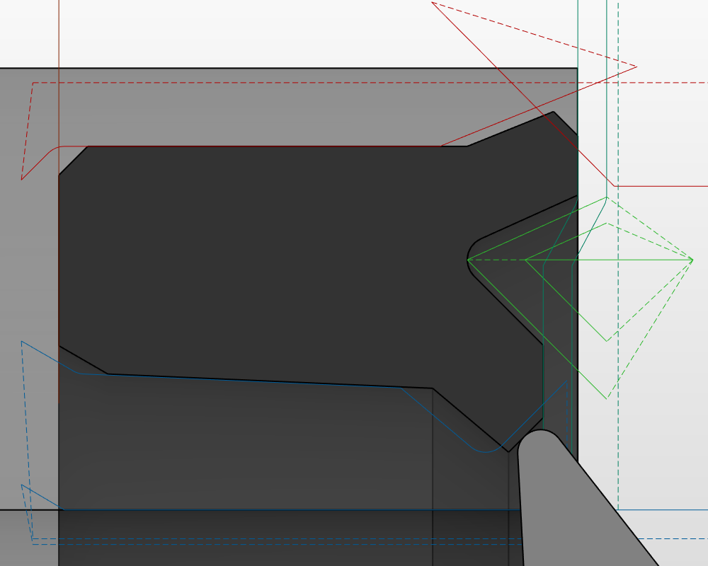
After the release of version 5.2.3.3 (August 2021), extra functionality was added regarding the tool tip direction. The changes introduced, can also change the behaviour of the tool path if the user does not update his tool database accordingly to the information on this post.
What is the tool tip direction?
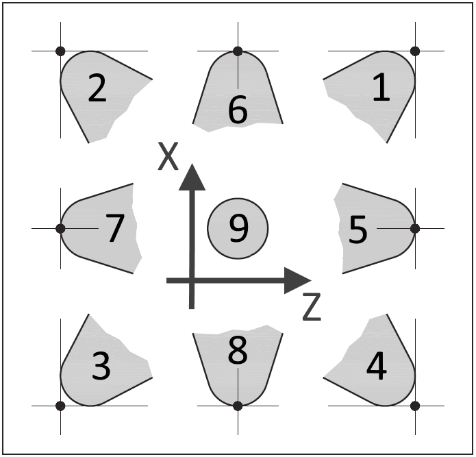
Generally speaking the tool tip direction informs the controller or the software regarding the cutting direction of the tool based on the diagram present below:
What did the latest changes affected?
We further enhanced the tool path generation and add extra functionality for the groove tools, that until now were not being using the tool tip direction and they were programmed internally. Based on the tool tip image shown before, now the tool tip setting for each grooving tool should be revised and confirmed if they match. If the tool tip settings is not correct the generated tool path can also be wrongly produced.
For demonstrations proposes, lets consider a outside groove tool and a simple shape. The same shape can be produced with the tool tip direction set with offset 3, 8 or 4.

- With the tool tip set to 3, the tool path is produced taken in consideration the most negative point off the tool in Z
- If the setting is 8, the tool path is generated based on the middle point of the tool
- Finally if the tool tip is set to 4, the tool path is generated based on the most positive Z value of the tool
The important aspect, and probably the most relevant is that the machine offset/calibration must be made in relation to the selected tool tip. If the offset/calibration does not match the tool tip on the software the produced tool path will be incompatible.
Since all previous outside groove code, was generated based on tool direction 3 even if another value was introduced on the tool database, we recommend that outside groove tools are set to 3 and for the same reasons all inside groove tools are set to 2. If this is checked/changed, no change is necessary on the tool offset.
More insight on tool radius compensation – know more
The tool tip direction was introduced in lathe machines because off the tool radius correction. Lathe tools generally have a radius that greatly influence the generated tool path in relation to the programmed tool path (programmed tool path = desired final shape).
The programmed tool path on a lathe would be the same as the generated tool path if the used tool would have radius equal to zero (see image below), but on a lathe, tools normally have a non zero radius.
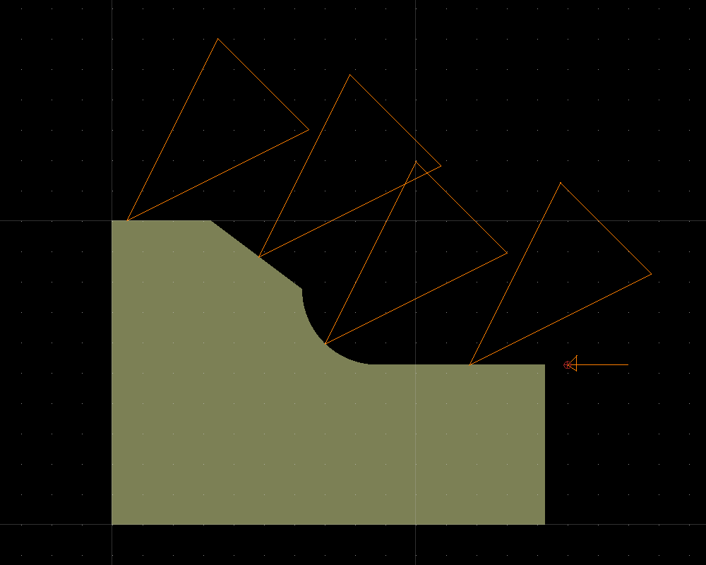
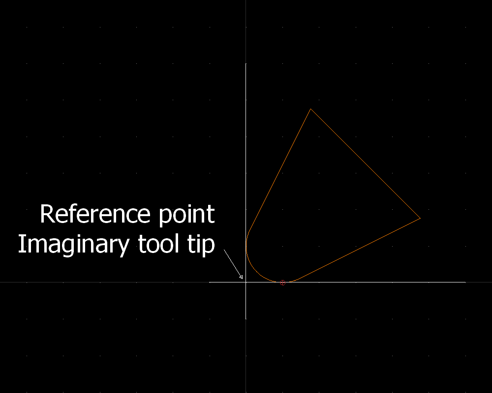
The controller or the software must then compensate the radius present on the tool so that the machined part is the most approximated possible to the programmed one. This is normally called tool path compensation and it is based on both the tool radius and on the tool direction.
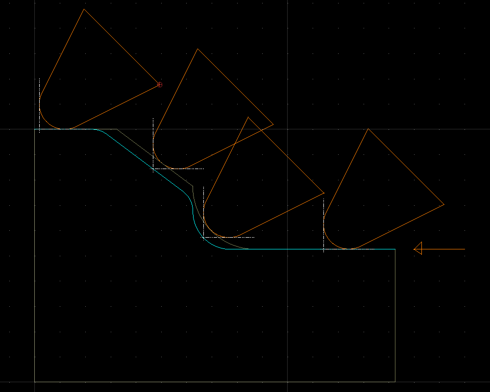
The FastSealCreator software produces the tool path already compensated based on the settings of the tool database. This is the reason that the tool path shown on the software does not match the profile shape, but the machined part will.
